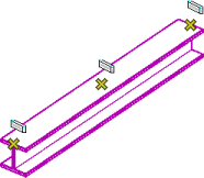
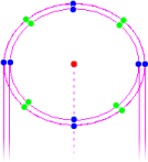
Structural Member Keypoints
Building form and component keypoints are designed to work with associative dimensioning as a means of identifying points where associative dimensions can be placed. When changes or modifications are made to the dimensioned form or component, the associative dimensions update. These keypoints are in addition to the default element keypoints which are identified by tentative snap points, and Structural Snap keypoints which are distinguished from others by a special cursor icon.
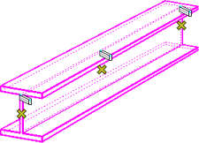
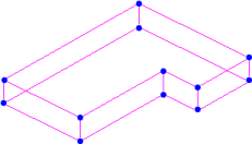
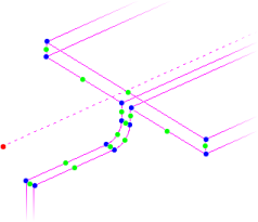
The following section illustrates available keypoints for
associative dimensioning functionality for the various Structural
member types. To simplify the discussion, the arrangement of keypoints depicted
reflects the default condition of the application with respect to the keypoint
divisor. By default, it is set to a value of two, dividing all elements into
two equal segments. Color coded keypoints illustrated here are for reference
only and do not appear in the interface: